Hydraulic Equipment
Main text
NRP Series POWER PACKAGE
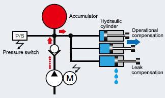
Example system configuration
(machining center cramp)

The unit accumulates pressure in the accumulator and stops the electric motor with the set upper pressure limit of the pressure switch. Using the oil pressure accumulated in the accumulator, the unit maintains the pressure of the circuit and carries out
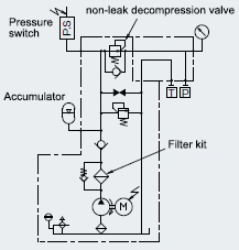
Hydraulic circuit diagram

- The pressure switch, accumulator, filter kit, and non-leak decompression valve re options. Select them in accordance with the application.
Package Specifications
| NRP-10-12-10 | NRP-10-24-10 | Remarks | |
|---|---|---|---|
| Pump capacity | 3.0cm3/rev | 5.0cm3/rev | |
| Motor output - No. of poles | 1.2kW-4P | 2.4kW-4P | S3:Repeated operation |
| Load operation hour rate (per minute) |
15%(9sec) | 10%(6sec) | S2:The operation time is a maximum of 3 minutes |
| Specifications tank | Resin tank (10 liters) | ||
| Specifications option | |||
| Pressure switch | One output point (open collector) | Pressure fixing type | |
| Accumulator | 0.7Lit | ||
| Non-leak decompression valve | Pressure adjustment range: 2.0 - 7.0MPa | ||
| Specifications tank | Steel plate tank (10 liters) | The steel plate tank is a special figure number | |
Explanation of model No
